



Why Use a Scaffold Jack Base for Better Support?
A scaffold begins at ground level, where small errors can become serious instability. A Scaffold Jack Base helps distribute vertical loads across a larger surface. It also supports accurate leveling on uneven work areas. This matters when frames carry workers, boards, tools, and shifting materials.
OSHA’s Scaffold Safety Fact Sheet reports about 4,500 scaffold-related injuries and 50 fatalities annually in the United States. OSHA also identifies unstable foundations, missing components, and improper assembly as recurring hazards. The CPWR Data Center continues to report falls as a leading cause of construction deaths. These findings show why base support deserves more attention.
“Stable support is the first control against scaffold movement.” — John W. Chitty, scaffold-safety consultant
A properly adjusted jack base can improve contact and reduce rocking. It should sit on a firm, load-bearing surface, not loose soil, scrap timber, or stacked blocks. OSHA Standard 1926.451(c)(2) requires scaffold footings to be level, sound, rigid, and capable of supporting the intended load.
The detail feels simple.
It is often neglected.
Real job sites are rarely perfect. Rain softens soil. Concrete slopes slightly. Workers may adjust one jack without checking the entire bay. That shortcut can create uneven loading, even when the scaffold looks acceptable. A Scaffold Jack Base is not a complete safety solution. It works only with competent inspection, correct installation, proper bracing, and manufacturer guidance.
The overlooked weakness is usually human judgment. Better equipment helps, but disciplined installation still decides whether support remains dependable.
Why Use a Scaffold Jack Base for Better Support?
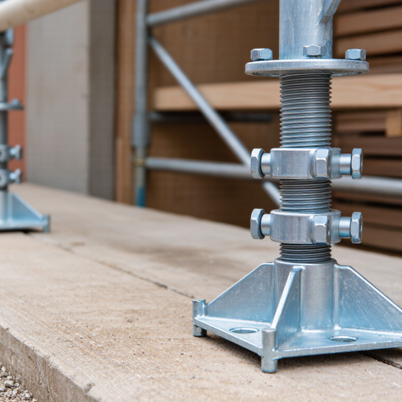
A scaffold jack base is an adjustable support installed beneath a scaffold frame or standard. It usually combines a steel base plate, threaded stem, and height-adjusting collar. The base plate spreads pressure across the supporting surface. The threaded stem allows workers to correct small height differences on sloped or uneven ground.
It is not a magic leveler.
During setup, workers turn the collar gradually until the scaffold stands plumb. A spirit level should confirm the adjustment from several directions. The base must sit on a firm foundation, often with a suitable mud sill or sole board. U.S. OSHA Standard 1926.451 requires scaffold legs and frames to bear on base plates, mud sills, or other adequate foundations. It also requires supported scaffolds to support their maximum intended load with a safety factor of four.
That detail matters under real jobsite conditions. A loaded platform can shift when materials are stacked near one edge. OSHA safety materials estimate that scaffold-related incidents cause about 4,500 injuries and 50 deaths annually in the United States. A jack base helps distribute load, but it cannot repair weak soil, damaged threads, or careless assembly. I have seen small height corrections become unstable when workers extended jacks too far. The manufacturer’s limits and the project’s engineered plan still control the setup. Misjudgment happens. Regular inspection remains necessary.



Copyright © CUSTOM Building Products 2025
Products | Resources | Interactive Tools | Warranties | Privacy Policy | Terms of Use | Technical Training
